27+ years engineering industrial gearboxes for demanding torque applications. From 1.5kW to 400kW. Planetary, helical, worm, and cycloid configurations. Engineered for mining, steel, port, and heavy manufacturing operations worldwide.
Each configuration serves specific torque, speed, and environment requirements. Engineering selection is determined by your application parameters — not by catalog popularity.
Sun gear surrounded by planet gears inside a ring gear. Load distributed across multiple contact points. High torque density for heavy-duty industrial transmission applications.
Parallel-axis helical gears with angled tooth engagement. Designed for smooth, low-noise operation under continuous industrial duty conditions. Higher efficiency across full load range. Standard for most industrial power transmission.
Worm gear geometry provides compact right-angle reduction with self-locking capability for positioning and lifting applications. Lower efficiency at high ratios — verify thermal capacity.
KHV cycloidal reduction combined with needle roller bearing support provides high shock-load resistance and compact torque transmission, providing an effective solution for applications requiring compact dimensions and high torque capacity.
Gear reducers engineered for continuous-duty industrial environments, shock loading, thermal stress, and contamination-intensive applications.

Gear reducers are rated for continuous 24/7 operation without thermal derating. Lubrication schedules and maintenance intervals are calculated according to operating temperature and duty cycle for maximum reliability.

Case-hardened gear teeth and reinforced bearing arrangements handle repeated impact loads from crusher strikes, steel slab impacts, and hoist operations. Service factor ≥1.5 for heavy shock applications.

Thermal rating verification for ambient temperatures up to +55°C. Enhanced cooling fin designs and synthetic lubricant options extend operational life in hot industrial environments.

Double-lip output seals and labyrinth input seals provide IP65/IP66 protection against fine particulate contamination common in mining, cement, and grain handling environments.

Frequent motor starting duty requires reinforced bearing load ratings and thermal capacity verification. Specify service factor ≥1.5 for cyclic duty applications exceeding 10 starts per hour.

Uninterrupted operation design. Bearings rated L10 ≥50,000 hours at rated load. Lubrication schedules are provided with each unit. Oil change intervals are calculated according to application duty cycle.
Correct gearbox selection depends on load characteristics, operating conditions, and service factor verification.
Calculate the torque required at the output shaft:
Verify the result is below the gearbox rated torque at the target ratio. Undersizing reduces bearing life and increases gear stress under shock loading conditions. Never select a gearbox by motor power alone.
Ratio = Motor Speed ÷ Desired Output Speed. Confirm the selected gearbox covers the required ratio range AND torque capacity at that ratio simultaneously. A ratio that falls within the gearbox range does not guarantee sufficient torque rating at that ratio. Both parameters must be verified together.
Ambient temperature range, dust and moisture levels, and corrosive agents determine housing material, seal specification, and paint system. Gray cast iron or ductile iron housing. IP65 or IP66 seals. ISO 12944 C2 to C4 marine paint systems. Standard ambient: −15°C to +45°C. Extended range available for non-standard environments.
Continuous duty (24/7), intermittent duty, and heavy start-stop each require different thermal ratings and service factors. Specify exact daily operating hours and number of motor starts per hour. Service factor 1.25 for uniform loads. Service factor 1.5–2.0 for shock or intermittent loads. Thermal verification is required for all cyclic duty applications.
Three standard configurations: Foot-mounted (bolted to baseplate), Flange-mounted (IEC B3/B5 input flange for direct motor coupling), and Shaft-mounted or hollow bore (output shaft accepts driven equipment shaft). Mounting configuration affects shaft alignment, structural loading, and maintenance accessibility. Specify based on equipment layout and installation constraints.
Lubrication specification and maintenance intervals are calculated according to operating temperature and duty cycle for maximum equipment reliability. Oil bath splash lubrication is standard. Forced circulation lubrication is required for high-power or high-ambient applications. ISO VG 150–680 gear oil selected per operating conditions. Extended temperature configurations use synthetic lubricants. Lubrication schedule provided with every unit.
Gearbox service life is determined by engineering decisions in design, materials, and manufacturing — not catalog ratings.

20CrMnTi case-hardened steel, precision-ground teeth. Surface hardness 55–62 HRC at tooth surface, core hardness 28–35 HRC for toughness at the tooth root. Handles shock loads and resists brittle fracture at the gear tooth root.

HRB / LUOYANG industrial-grade cylindrical roller and angular contact bearings. L10 ≥50,000 hours at rated load. Bearing loads specified with 1.5× service factor above calculated bearing loads. Inadequate bearing rating is the most common cause of premature gearbox failure.

Cooling fins on all housings. Operating temperature −15°C to +45°C standard, −30°C to +55°C extended range. Each unit verified thermally at rated power before dispatch. Heat generation directly affects oil service life and lubrication interval.

Double-lip output seals prevent contamination ingress in high-dust environments. Input-side labyrinth seals provide a second barrier. Modular housing design allows seal replacement without removing the gearbox from the driven equipment.

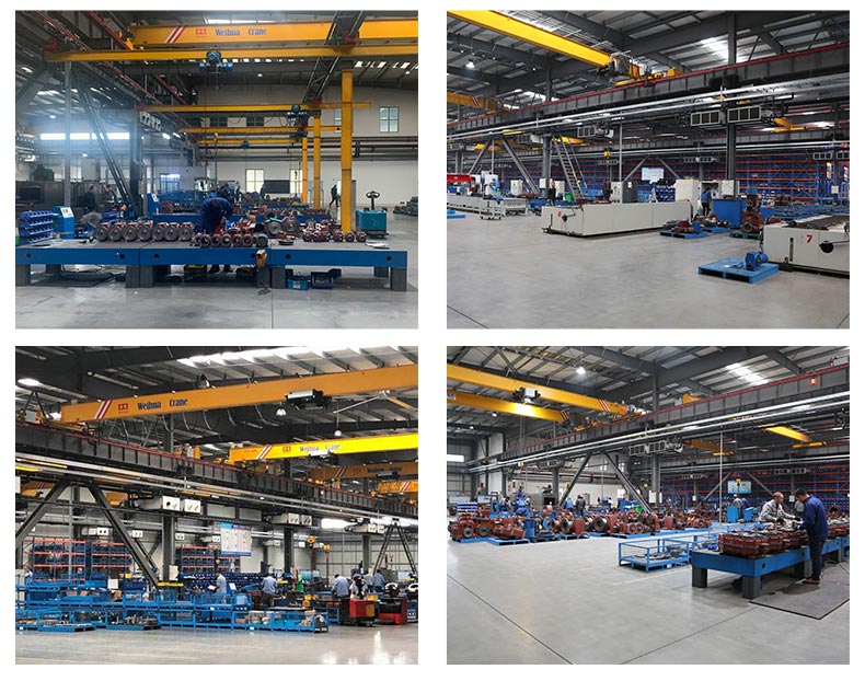
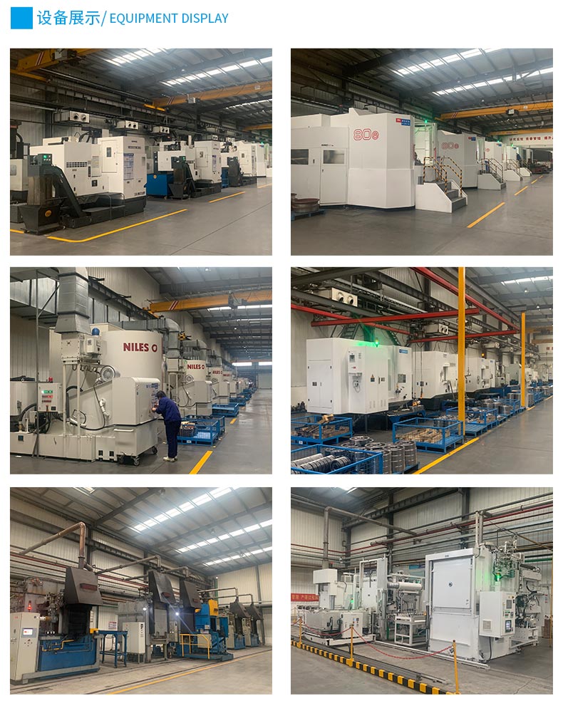
Every gearbox undergoes no-load and full-load test runs before dispatch. Test reports included with each shipment. Material certificates (EN10204 3.1) available on request for pressure-containing components.

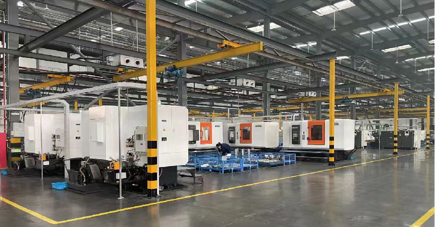
FC200/FC250 gray cast iron or FCD500 ductile iron housings. Precision-machined mounting faces and bearing bores to H7 tolerance ensure correct bearing preload, shaft alignment, and long-term dimensional stability under load.
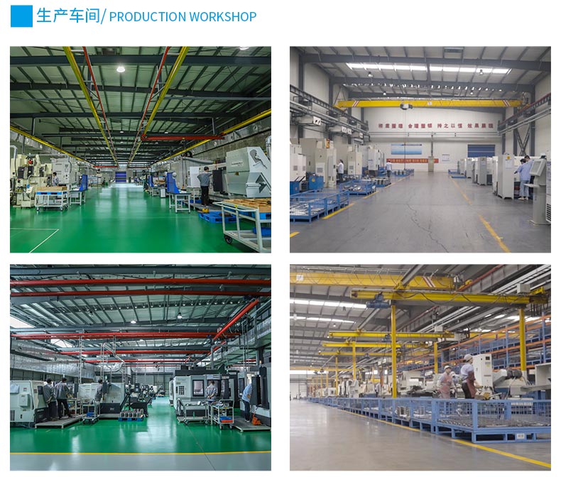
Engineering parameters verified for continuous-duty industrial power transmission applications. Custom configurations available for non-standard operating conditions and installation requirements.
| Parameter | Specification |
|---|---|
| Core Performance | |
| Torque Range | 180 – 400,000 Nm |
| Motor Power | 1.5 – 400 kW |
| Gear Ratios | 1:5 – 1:1000+ (multi-stage) |
| Output Speed Range | 7.5 – 360 rpm |
| Efficiency | Planetary-helical: ≥94% (two-stage) / Worm reduction: ≥65–88% depending on ratio |
| Configuration | |
| Gear Types | Planetary / Helical / Worm / Cycloid |
| Stages | Single / Two / Three |
| Mounting Configuration | IEC B3/B5 Flange / Foot Mount / Shaft Mount / Hollow Bore |
| Output Shaft Options | Solid / Hollow bore / Splined / Tapered |
| Materials & Service Life | |
| Housing Material | FC200/FC250 Gray Cast Iron / FCD500 Ductile Iron |
| Gear Material | 20CrMnTi case-hardened steel, precision-ground teeth |
| Surface Hardness | 55–62 HRC |
| Bearing Type | HRB / LUOYANG cylindrical roller and angular contact bearings |
| Bearing L10 Life | ≥50,000 hours at rated load |
| Operating Conditions | |
| Protection Grade | IP65 / IP66 |
| Operating Temperature | −15°C to +45°C (standard) / −30°C to +55°C (extended) |
| Cooling Options | Natural cooling fins / Forced oil circulation / External cooler |
| Lubrication Type | ISO VG 150–680 synthetic or mineral gear oil (bath splash or forced) |
| Paint System | Industrial epoxy primer + PU top coat (ISO 12944 C4) |
| Certification & Testing | |
| ATEX Certification | II 3G Ex ec IIC T4 Gc / II 2D Ex tb IIIB T130°C |
| Test Run | 100% no-load and full-load verification before dispatch. Test reports included with shipment. |
Industrial gear reducers convert high-speed motor input into controlled low-speed, high-torque output required for heavy-duty industrial equipment.
Output torque is determined by motor power, gear ratio, and efficiency — not by catalog ratings alone. All three parameters must be verified together during specification.
Answers to common technical questions for selecting and applying industrial gear reducers. Focused on torque, service factor, bearing life, and gearbox configuration for industrial applications.
Provide your motor power, output speed, torque requirement, application type, and operating conditions. Our engineering team will verify gearbox sizing, service factor, mounting configuration, and thermal suitability before quotation.